ffglitch jpeg dc coefficients

Glitching images with hex editors is fun. We touch a few bytes and the whole image gets screwed up.

But what if we don’t want to screw up the bitstream? I want the resulting bitstream to valid, and just tweak a few values.

I had an idea on how to do that, and I’ve spent a few hours this weekend working on a proof of concept for FFmpeg. The source code is available here:

https://github.com/ramiropolla/ffmpeg/tree/gbm

Basically it’s a three-step process. We first run FFmpeg and ask it to dump the value we’re interested in editing (only DC coefficients for jpeg images is currently implemented). We then tweak the values that were dumped in a text file. And then we re-run FFmpeg and specify the altered dump file as input for those specific values.

The code is a huge hack. I’ve modified the jpeg decoder to dump the DC coefficients on the first run. Then I’ve modified the bitstream reader to duplicate the data it’s reading as it goes along. When we get to the altered DC coefficients, the new values are read from the text file and written to the output bitstream.

$ ./configure --disable-everything --disable-external-libs --disable-doc --disable-programs --enable-ffmpeg --enable-decoder=mjpeg --enable-encoder=mjpeg --enable-encoder=mjpeg_glitch --enable-demuxer=image2 --enable-muxer=image2
$ make
$ # generate DC coefficients file
$ ./ffmpeg_g -i lena.jpg -f image2 -vcodec mjpeg_glitch -dump_mjpeg_dc dc_in.txt -y temp.jpg
$ # now edit dc_in.txt (for example, using the python script provided with the source code)
$ python glitch/reverse_dc.py dc_in.txt > dc_out.txt
$ # rewrite the bitstream with the new DC coefficients
$ ./ffmpeg_g -i lena.jpg -f image2 -vcodec mjpeg_glitch -read_mjpeg_dc dc_out.txt -y lena_out.jpg

Input:

lena

Output:

lena_out

ffglitch pixel formats

This weekend I was at the Poetic Computation Group Belgium and Greg Berger mentioned doing glitch art with FFmpeg.

Being a former FFmpeg developer myself, I remembered having made quite a bunch of experimentation with it, but it was mostly ephemeral and just for fun. Then I thought to myself: what about turning those bits and pieces of experimentation into blog posts and projects on GitHub?

And so the first project is born into my very new ffglitch repository. The name of the repository suggests more FFmpeg glitch art projects will come, and I hope my laziness doesn’t stop me from doing this (which it likely will).

pix_fmt

https://github.com/ramiropolla/ffglitch/tree/master/pix_fmt

The pix_fmt project consists of doing a whole bunch of incorrect pixel format conversions. If you don’t know what pixel formats are, read up on my previous blog post pixel formats 101.

The project is a script that generates a bunch of combinations for pixel format conversion. For example,  one such conversion takes raw RGB data as input, pretends that data is YUV420p, and reconverts it to RGB. The project does this for all possible input to output pixel format combinations. This amounts to nearly 10000 images, with about 4000 being unique.

To try it out, just do:

$ git clone https://github.com/ramiropolla/ffglitch.git
$ cd pix_fmt
$ python pix_fmts.py <input.png> > makefile
$ make -r -k -jN
$ cd output_dir
$ fdupes --delete --noprompt .

What are the results like? Well, here are some samples (originals first):

libcaca logo:

libcaca-logoyuvj444p_yuv420p12le yuva422p9le_yuv420p16be yuva422p9be_yuv444p14le yuv444p16be_yuv420p14be yuv444p12le_yuv444p16be xyz12be_yuv420p10le  gbrp_yuvj440p gbrp9be_yuv422p10le gbrp9be_bgr48le gbrp12le_yuv420p10le

Tarrafa hackerspace logo with yellow background:

argb_argbyuva444p_yuv422p12le yuv444p16le_yuv422p14le yuv444p16le_yuv422p12le gbrp10be_xyz12le bgr48be_yuv444p14be

Tarrafa hackerspace logo with white background:

argb_argb bgr24_yuv444p.png

Check it out, make your own ffglitch.pix_fmt and post the link in the comments!

Have fun…

pixel formats 101

How is an image represented in the computer’s memory?

There are a billion different file formats, codecs, and pixel formats that can be used for storing images. Think BMP, PNG, WEBP, BPG, GIF (pronounced JIF), lossy, lossless, whatever…

But at some point, the image is read from disk, demuxed, decompressed, and then we have a bunch of data in the computer’s memory. It is raw data. Just pixels. What is that raw representation of pixels like?

You’ve probably heard of RGB. The simplest answer could be:

First there’s a red pixel, then a green pixel, then a blue pixel, and so on and so on…

rgbrgbrgb

Great. Kind of. In that case, each pixel would be spread out through its three components, so we would have

one pixel, then another pixel, then another pixel, and so on and so on…

and for each of those pixels, we would have

one red component, then one green component, then one blue component.

pixel_rgbrgbrgb
pixel_rgbrgbrgb

But images are bidimensional. They are made up of many lines stacked one on top of the other. The computer’s memory is just one long line. Should we have one RAM stick for each line of our image?

Of course not, we just put the lines one next to the other. So now we have:

Pixel 1 from line 1, pixel 2 from line 1, …, pixel n from line 1, pixel 1 from line 2, pixel 2 from line 2, …, pixel n from line 2, …, …, …, …, pixel 1 from line m, pixel 2 from line m, …, pixel n from line m.

where n is the width of one line and m is the height of the image.

line_pixel_rgbrgbrgb

If each component for each pixel is 1 byte, then each pixel is 3 bytes, each line is n * 3 bytes, and the entire image is m * n * 3 bytes.

Now let’s see another pixel format: YUV. It is very widely used for lossy video codecs and lossy image compression because it can easily deal with the fact that our eyes perceive brightness better than color. Each pixel is transformed into one component for luminance (roughly equivalent to brightness), and two funky values describing color information. We will call those components Y (luminance), U and V (chrominance). Let’s suppose they’re also 1 byte for each component.

So, for this pixel format, we just do the same as with RGB, but storing the YUV components instead, right? Like so:

one Y component, then one U component, then one V component, and so on and so on…

line_pixel_yuvyuvyuv

Sure, we could, but that’s not normally what we do. Remember that our eyes are better at perceiving luminance than chrominance? What happens if we throw away half of the information related to chrominance? Well, we still get a pretty darn good looking image. What we have now is:

one Y component, then one U component, then another Y component, then one V component, and so on and so on…

line_pixel_yuyvyuyvyuyv

Remember that the RGB image used n * m * 3 bytes? The YUV image with half the color information thrown out will take n * m bytes for Y, and n * m for both U and V combined, for a total of n * m * 2 bytes. Heck, we just cut the image size by 33%!!! and it still looks good (search on google for image comparisons, I’m too lazy to make them myself). In the image above, even though it’s smaller, we now described 4 pixels per line instead of 3.

But that’s not all the fun we can get out of YUV. Suppose you have an old black and white film (actually, what we call black and white in this case is really grayscale. It’s not only 100% black or 100% white pixels. It will encompass many shades of grey between full black and full white).

So suppose you have a film with many shades of grey. There is no color information at all in there. Then why are we wasting precious disk space or precious memory with all three Y, U, and V components? We can just throw away U and V entirely and still have the exact same output on our screens. We just cut the image size by 66% in regards to the original image!!! What we have now is:

one Y component, another Y component, another Y component, and so on and so on…

line_pixel_yyyyyyyy
line_pixel_yyyyyyyy

Now suppose you have a film that does have color, but some people watching it might be stuck with black and white TVs. Some viewers will get the colored stuff, other viewers only care about the Y. Therefore we HAVE to transmit Y, U, and V. But then, black and white TVs will have to sift through the data and select only the Y components. It will have to do:

get Y component, drop U component, get Y component, drop V component, get Y component, drop U component, get Y component, drop V component, and so on and so on…

line_pixel_yuyvyuyvyuyv_nouv

If only there was a way to sort the Y, U, and V data in a way that made it simpler to select each specific type of components… Oh, wait, there is a way! It’s called planar YUV. It’s all still the same data, but the way they’re represented in memory will look like:

plane 1: one Y component, another Y component, another Y component, and so on and so on…
plane 2: one U component, another U component, another U component, and so on and so on…
plane 3: one V component, another V component, another V component, and so on and so on…

line_pixel_planar_yuv

Now that black and white TV set can just get the Y plane, and then drop the entire U and V planes.

line_pixel_planar_yuv_nouv

There’s a shitload more of pixel formats around. There are higher bit-depths (9, 10, 16 bits per pixel, both in little-endian and big-endian), YUV with interleaved UV, paletted formats (remember old arcade consoles?), YUV formats that drop a bunch more color information (both horizontally and vertically), different component orders for RGB (i.e. BGR)… Just look at this list created by ffmpeg -pix_fmts:

$ ffmpeg -pix_fmts
ffmpeg version N-69925-g9f6431c Copyright (c) 2000-2015 the FFmpeg developers
  built with Ubuntu clang version 3.4-1ubuntu3 (tags/RELEASE_34/final) (based on LLVM 3.4)
  configuration: --enable-libmp3lame --enable-libx264 --cc='ccache clang' --enable-gpl
  libavutil      54. 18.100 / 54. 18.100
  libavcodec     56. 22.100 / 56. 22.100
  libavformat    56. 22.100 / 56. 22.100
  libavdevice    56.  4.100 / 56.  4.100
  libavfilter     5. 11.100 /  5. 11.100
  libswscale      3.  1.101 /  3.  1.101
  libswresample   1.  1.100 /  1.  1.100
  libpostproc    53.  3.100 / 53.  3.100
Pixel formats:
I.... = Supported Input  format for conversion
.O... = Supported Output format for conversion
..H.. = Hardware accelerated format
...P. = Paletted format
....B = Bitstream format
FLAGS NAME            NB_COMPONENTS BITS_PER_PIXEL
-----
IO... yuv420p                3            12
IO... yuyv422                3            16
IO... rgb24                  3            24
IO... bgr24                  3            24
IO... yuv422p                3            16
IO... yuv444p                3            24
IO... yuv410p                3             9
IO... yuv411p                3            12
IO... gray                   1             8
IO..B monow                  1             1
IO..B monob                  1             1
I..P. pal8                   1             8
IO... yuvj420p               3            12
IO... yuvj422p               3            16
IO... yuvj444p               3            24
..H.. xvmcmc                 0             0
..H.. xvmcidct               0             0
IO... uyvy422                3            16
..... uyyvyy411              3            12
IO... bgr8                   3             8
.O..B bgr4                   3             4
IO... bgr4_byte              3             4
IO... rgb8                   3             8
.O..B rgb4                   3             4
IO... rgb4_byte              3             4
IO... nv12                   3            12
IO... nv21                   3            12
IO... argb                   4            32
IO... rgba                   4            32
IO... abgr                   4            32
IO... bgra                   4            32
IO... gray16be               1            16
IO... gray16le               1            16
IO... yuv440p                3            16
IO... yuvj440p               3            16
IO... yuva420p               4            20
..H.. vdpau_h264             0             0
..H.. vdpau_mpeg1            0             0
..H.. vdpau_mpeg2            0             0
..H.. vdpau_wmv3             0             0
..H.. vdpau_vc1              0             0
IO... rgb48be                3            48
IO... rgb48le                3            48
IO... rgb565be               3            16
IO... rgb565le               3            16
IO... rgb555be               3            15
IO... rgb555le               3            15
IO... bgr565be               3            16
IO... bgr565le               3            16
IO... bgr555be               3            15
IO... bgr555le               3            15
..H.. vaapi_moco             0             0
..H.. vaapi_idct             0             0
..H.. vaapi_vld              0             0
IO... yuv420p16le            3            24
IO... yuv420p16be            3            24
IO... yuv422p16le            3            32
IO... yuv422p16be            3            32
IO... yuv444p16le            3            48
IO... yuv444p16be            3            48
..H.. vdpau_mpeg4            0             0
..H.. dxva2_vld              0             0
IO... rgb444le               3            12
IO... rgb444be               3            12
IO... bgr444le               3            12
IO... bgr444be               3            12
I.... ya8                    2            16
IO... bgr48be                3            48
IO... bgr48le                3            48
IO... yuv420p9be             3            13
IO... yuv420p9le             3            13
IO... yuv420p10be            3            15
IO... yuv420p10le            3            15
IO... yuv422p10be            3            20
IO... yuv422p10le            3            20
IO... yuv444p9be             3            27
IO... yuv444p9le             3            27
IO... yuv444p10be            3            30
IO... yuv444p10le            3            30
IO... yuv422p9be             3            18
IO... yuv422p9le             3            18
..H.. vda_vld                0             0
IO... gbrp                   3            24
IO... gbrp9be                3            27
IO... gbrp9le                3            27
IO... gbrp10be               3            30
IO... gbrp10le               3            30
I.... gbrp16be               3            48
I.... gbrp16le               3            48
IO... yuva420p9be            4            22
IO... yuva420p9le            4            22
IO... yuva422p9be            4            27
IO... yuva422p9le            4            27
IO... yuva444p9be            4            36
IO... yuva444p9le            4            36
IO... yuva420p10be           4            25
IO... yuva420p10le           4            25
IO... yuva422p10be           4            30
IO... yuva422p10le           4            30
IO... yuva444p10be           4            40
IO... yuva444p10le           4            40
IO... yuva420p16be           4            40
IO... yuva420p16le           4            40
IO... yuva422p16be           4            48
IO... yuva422p16le           4            48
IO... yuva444p16be           4            64
IO... yuva444p16le           4            64
..H.. vdpau                  0             0
IO... xyz12le                3            36
IO... xyz12be                3            36
..... nv16                   3            16
..... nv20le                 3            20
..... nv20be                 3            20
IO... yvyu422                3            16
..H.. vda                    0             0
I.... ya16be                 2            32
I.... ya16le                 2            32
IO... rgba64be               4            64
IO... rgba64le               4            64
IO... bgra64be               4            64
IO... bgra64le               4            64
IO... 0rgb                   3            24
IO... rgb0                   3            24
IO... 0bgr                   3            24
IO... bgr0                   3            24
IO... yuva444p               4            32
IO... yuva422p               4            24
IO... yuv420p12be            3            18
IO... yuv420p12le            3            18
IO... yuv420p14be            3            21
IO... yuv420p14le            3            21
IO... yuv422p12be            3            24
IO... yuv422p12le            3            24
IO... yuv422p14be            3            28
IO... yuv422p14le            3            28
IO... yuv444p12be            3            36
IO... yuv444p12le            3            36
IO... yuv444p14be            3            42
IO... yuv444p14le            3            42
IO... gbrp12be               3            36
IO... gbrp12le               3            36
IO... gbrp14be               3            42
IO... gbrp14le               3            42
IO... gbrap                  4            32
I.... gbrap16be              4            64
I.... gbrap16le              4            64
IO... yuvj411p               3            12
I.... bayer_bggr8            3             8
I.... bayer_rggb8            3             8
I.... bayer_gbrg8            3             8
I.... bayer_grbg8            3             8
I.... bayer_bggr16le         3            16
I.... bayer_bggr16be         3            16
I.... bayer_rggb16le         3            16
I.... bayer_rggb16be         3            16
I.... bayer_gbrg16le         3            16
I.... bayer_gbrg16be         3            16
I.... bayer_grbg16le         3            16
I.... bayer_grbg16be         3            16

That’s it

That was a very very basic introduction about pixel formats. If you want to learn more about this, then you should go on and read the pixel format descriptors from the FFmpeg source code. Or else, if you’re not ready to spend a couple of years learning C and delving into the FFmpeg source code, just search on google. There is a bunch of information out there…

Have fun…


MESS Paper simulator

I haven’t played much with the ActionPrinter 2000 dot-matrix printer since last year. I had gotten MESS to emulate the printer’s firmware and used that to simulate the system’s printer using MESS, but the whole procedure was still kind of complicated, requiring exporting a bunch of logging information to a text file and using a script to convert that to a picture.

I finally got over my laziness and implemented an output device to simulate the paper being printed out directly in MESS.

The paper emulation is actually pretty simple and dumb. A big bitmap is populated with the dots from the printer when the printhead fires. The lines in the bitmap form a circular buffer, and when paper is “pulled” from the printer, it just updates an index that points to some line in the buffer and clears the next line. MESS already had support for scrolling bitmap that by using the copyscrollbitmap() function.

This only covers continuous paper though… What I really want is to implement a paper_t class (subclassing device_t), which can have proper paper dimensions (A4, letter, etc…) and interacts with the paper-end sensor. That way, I hope to be able to output PNGs and PDFs directly from MESS.

The problem is that I haven’t had access to the real printer for an year and a half, and I don’t remember how the sensors and the paper interact =/. I’m trying to get my hands on a similar printer to continue working on this. Hopefully, it won’t take another year before I figure this out…


Reverse Engineering a 35 mm Animation Camera

Last week I visited Labor Berlin, an independent film laboratory dedicated to experimentation with motion picture film. They do everything film-related, from making their own chemical solutions to filming, processing, and screening, in all kinds of films (8 mm, 16 mm, 35 mm…). It is pretty much a hackerspace, but for film-related stuff.

One piece of equipment they had there was a Crass Tricktisch. It’s a film animation table and an animation camera, made by Crass GmbH.

Crass logo

The table and camera were given to Labor Berlin by L’Abominable, an independent French film laboratory just like them.

Basically, you have a table to draw your animation, a camera looking at the table from above, and a controller that lets you take single pictures, move the film forwards, backwards, and do some funky stuff like cross-fade.

Crass Tricktisch

They had a couple of cameras to use with the table, one super 16, and another 35 mm. The super 16 camera was connected to the animation table and they had already used it a few times, but the 35 mm camera had never been tested by them, since the connector was different, and wouldn’t attach to the table.

The Kamera

I got curious about how hard it would be to adapt the 35 mm camera to fit the connector, or vice-versa. We searched around in the Internet and found this website with some documentation about the table and the camera. These documents were written in the 60’s, 70’s, and some even in the 90’s. Part of the documents appear to be original technical manuals, others are hand-drawn, and others appear to be previous attempts at reverse-engineering. There was also a more official-looking manual at the laboratory with some nice drawings (like the image of the table above).

Kameraschaltung

The electrical schematics are a bit old-fashioned and they’re written in German, so I thought it would be easier to reverse-engineer the whole thing from the start than to try and understand German =).

I picked up a screwdriver and started opening the camera, taping each screw to a piece of paper with a description of where the screw came from. From my previous reverse-engineering endeavours, I know very well that it is important to document where each extracted part comes from. I don’t have a photographic memory, nor much of a good short term memory, so I usually end up with many pieces left after reassembly.

First view inside

After opening the first side, I could see the connector and the motor. The schematic had the description for the connector, but in all the manuals there were about 3 or 4 different description for cameras, so I didn’t know which one was correct. I opened up the whole camera, followed all the wires (even some tricky wires that turned out to be just stubs), tested all the pins, and came up with this schematic:

schematics

The camera uses one main motor to turn everything. It’s incredible how they managed to do everything mechanically. The same motor takes care of pulling the film, activating the shutter (in 3 different selectable speeds!), activating the film break system (so that the film is stopped while the shutter is open), counting the number of frames, and probably other things that I can’t remember right now.

The shutter uses a sliding window to give different exposure times, and there are two micro-switches directly related to the shutter. One of them changes state when the shutter is about to open, and the other changes state when the shutter is about to close.

The sliding shutter window uses an electrical circuit connected to a mechanical system to give the proper exposure time. There’s a complex mechanical system that automatically changes the exposure time, in order to do fade-ins and fade-outs. I spent quite some time trying to understand all of it, but then just gave up, and decided I wouldn’t want to use it anyways.

Electro-mechanical shutter system
The electro-mechanical cross-fade system

I was interested in understanding how the motor was controlled. A label in the motor read:

dunkermotor
Typ: SY 52 x 60 - 2
Nr: 36124
24V 3000 U/min

There are three wires going into the motor, so it’s obviously a three-phase motor (also that’s what it says in the schematic). There didn’t seem to be any switches to turn the motor on or off in the camera itself. So it must have been the animation table that controlled the camera through the connector.

I plugged in the (working) super 16 camera into the table, and unscrewed the connector casing. The connections were (apparently) the same as in the 35 mm camera. When the camera was stopped, the multimeter accused anything from ~19 VAC to ~34 VAC between each two terminals of the motor, which seemed odd. Nothing was moving, so I just assumed it was some stray voltage with no actual power. I thought about touching it with my fingers to make sure there was no power, but then I paused for a second, thought some more, and reminded myself that a 30 VAC electrical shock can be quite annoying. With the camera running, the multimeter accused about 24.7 VAC between each two terminals of the motor. So now I knew, it was the animation table that switched the motor on and off, not the camera itself.

Tricktisch
Der Tricktisch – The Animation Table

I didn’t feel like opening the animation table to see the circuit inside, since it seemed quite simple: at some point, the motor is switched on by just feeding it three-phase power.

Crappy picture closeup on animation table knobs

There is one knob on the animation table that reads “Rückwärts / Vorwärts”, which means “reverse / forward”. If we switch that and turn the camera on again, it magically turns the motor in the other direction. The film runs backwards, the shutter runs backwards, everything runs backwards. How does the table change the motor direction? In a three-phase motor, it’s just a matter of switching any two phases. We’ll see more about this in another post.

What does this all mean in relation to the motor and the connector? It means that turning the camera is just a matter of feeding it three-phase power directly through the connector. To test this, we decided to use the super 16 camera to jump start the 35 mm camera.

Jump starting 35 mm camera
The three white wires are coming from the super 16 camera

Since at first we didn’t have the right tools to do this jump start, the wires were very delicately positioned in order to just touch the connectors. At any moment a wire could slip and cause a short circuit. Luckily, that didn’t happen.

We connected a continuity tester from a multimeter to the “shutter open” switch, so that we could test that the switches were working properly. In this video you can see the result of all the hard work we did:


Now we know how the camera works. We could just build a new connector that fits into the animation table and use the 35 mm camera. But, since we know how the camera works, we can do much more! We have control over the basic operation of the camera. We know how to move the film back and forth, and we know when the shutter opens and closes. We did all that just by connecting a few wires. We don’t need the animation table to do all the work for us. We can recreate a stand-alone circuit that controls the camera in any weird way that we can think about. Long exposures, multiple exposures, sensor-activated filming, time-lapse photography…

So, what’s the next step? Replacing the animation table by an Arduino and a simple electronic circuit =).

Faster MAME build times

MAME is quite a big project. It has 5538 C source files and 3304 header files (counting all 3rd party libraries). There are a total of 4416185 lines of code.

The source files’ extension is c, but the project is actually written in C++. The transition from C to C++ happened a few years ago, mainly led by Aaron Gilles. C++ is known[citation needed] to take longer than C to compile.

The result of all this is that MAME takes a very long time to build. With my Intel Core 2 Quad Q6600 running Ubuntu 14.04, it takes almost 2 hours to build MAME. In this post I will give a few tips on how to get faster MAME build times. Some tips are only available for a few operating systems.

1. Use clang instead of gcc

GCC is awesome. It’s the compiler that powers the open-source world. It’s been doing this for over 27 years. But some 11 years ago LLVM came along, and some 7 years ago came clang, now a serious contender in the compilers world.

You can specify the compiler you want to use while building MAME with the CC=<compiler> option.

$ time make CC=clang
[...]
real    72m44.722s
user    65m47.202s
sys 4m57.559s

If you don’t want make to print out all compilation commands, just use the @ sign before the compiler name, like this: make CC=@clang

How much of a speedup do we get by using clang instead of gcc? Let’s find out.

$ time make CC=gcc
[...]
real    111m37.837s
user    102m32.533s
sys 8m31.289s

The speedup for a full build of MAME is 35% when using clang instead of gcc.

Clang is now the default compiler in Mac OS X, so there’s no need to specify it in the command line. Unfortunately, clang still does not support Windows.

2. Use multiple cores

With most processors now having multiple cores it’s quite straight-forward that we should be using all those cores for compilation. The compiler itself is not optimized for multiple cores, but since we have a bunch of files to compile and they’re independent of each other, we can compile them in parallel.

You can specify the amount of jobs to run in parallel with the -j <number of cores> option.

With GCC and two cores we get the compilation time cut almost by half:

$ time make -j2
[...]
real    54m45.346s
user    98m30.421s
sys 8m37.893s

Use as many cores as you can for compilation. It may even be worth using more jobs in parallel than actual number of cores. A good rule is to use <number of cores + 1> jobs.

3. Disable GNU make builtin rules

Up to now we’ve covered speedups for building the whole project. But what if you’re hacking away in MAME, and you have to compile your code over and over with small changes in between each run? The 30 seconds it takes to compile that one change and link MAME seem like FOREVER. Every second that can be scraped off is welcome.

Every time you run GNU make, it will check for all the files that have to be recompiled. If you have changed only one file, make will still check for all other files to see if they have to be recompiled. This is normally quite quick, but GNU make has a thing called implicit rules. It will check for a bunch of other files that you never asked for in the first place. I don’t know when this is really useful, but most modern Makefiles don’t need to use any implicit rules. MAME doesn’t.

You can disable this feature with the -r option.

To show the benefits of disabling implicit rules, I’ll run make in a fully built directory. Everything has already been built, so there’s nothing for make to do, except for checking if it needs to make any more rules, implicit or explicit.

On a system with no files cached (cache cleared between runs):

$ time make
make: Nothing to be done for `default'.

real    0m2.136s
user    0m0.577s
sys 0m0.120s

$ time make -r
make: Nothing to be done for `default'.

real    0m0.736s
user    0m0.119s
sys 0m0.122s

When all files already in cache:

$ time make
make: Nothing to be done for `default'.

real    0m0.550s
user    0m0.504s
sys 0m0.046s

$ time make -r
make: Nothing to be done for `default'.

real    0m0.128s
user    0m0.086s
sys 0m0.042s

The gains are very small on most systems (Linux and Mac OS X), being less than 2 seconds in the worst-case scenario. But let’s try this on Windows now:

> timer make
make: Nothing to be done for `default'.

time taken: 4164 ms

> timer make -r
make: Nothing to be done for `default'.

time taken: 472 ms

Did you see that? Instead of taking 4.164 seconds, make now takes only 472 milliseconds. The gains are HUGE in Windows systems, where file system operations take an awkwardly long amount of time.

4. Use gold

Suppose we’re still hacking MAME and making small changes in one source file only. Even if we have to compile only one file, we still have to link the MAME executable in its entirety. This means walking through all compiled object files to make one final executable. This step can take considerably longer than compiling any source files that have changed.

GNU binutils has a new linker optimized for ELF files and big C++ projects since 2008. This linker is called gold. It does a very good job with MAME.

You can specify the linker you want to use while building MAME with the LD=<linker> option.

You don’t use LD=gold directly, but specify that you want g++ to use gold while linking. The command thus becomes: LD="g++ -fuse-ld=gold"

Let’s see how much speedup we can get with gold instead of the default linker:

$ rm -f mame64 && time make -r
Linking mame64...

real    0m20.442s
user    0m16.478s
sys 0m2.757s

$ rm -f mame64 && time make LD="@g++ -fuse-ld=gold" -r
Linking mame64...

real    0m5.012s
user    0m4.185s
sys 0m0.781s

The linking step is 75% faster when using gold.

Unfortunately this linker only works for generating ELF files, which means it only works for Linux builds. Mac OS X and Windows can’t use this linker.

Putting it all together

So, different Operating Systems have different tricks to speedup MAME build times.

For Linux, use clang and gold:
$ make -r CC=@clang LD="@g++ -fuse-ld=gold" -j4

For Mac OS X, clang is used by default, and you can’t use gold:
$ make -r -j4

For Windows, you can’t use clang or gold, but at least you can use multiple cores and shave a few seconds off by disabling implicit rules:
> make -r -j4


Using MESS as the system’s printer

What was the main reason I started MESSing with the ActionPrinter 2000? To extract the characters’ bitmaps so that I could optimize image->ASCII conversion to the printer’s specific font.

As a fun side-project I decided to configure MESS with CUPS as a normal printer on my system to see how well it would work.

I started off by implementing the Centronics communication used by the printer in MESS. This way, it was possible to boot any device with a Centronics interface connected to the printer, as if I was actually running a device and the printer itself. For this, I booted a simple 486 with an MS-DOS 6.22 floppy disk inside MESS.

486

The parallel port communication with the printer was a little bit tricky.

ActionPrinter 2000 Centronics Interface Overview

When a strobe pulse is detected, the E05A30 gate array sets the BUSY signal. When the CPU is done reading the data and it’s time to unset the BUSY signal, the firmware does the following:

  1. Read the control register (which contains the ACK and BUSY signal) to a CPU register;
  2. Unsets the ACK signal in the CPU register and outputs everything to the control register;
  3. Unsets the BUSY signal in the CPU register and outputs everything to the control register;
  4. Sets the ACK signal in the CPU register and outputs everything to the control register.

The printer’s manual had conflicting information about which component was supposed to take care of setting/resetting the BUSY signal. Another printer’s manual (the LX-1050+, which uses the exact same gate array), had even more conflicting information about the Interface overview.

Besides that, the 486 I was using with the printer would ignore the ACK signal from the printer. The result was that between steps 3 and 4, the BUSY signal was unset, so the PC would ignore the ACK signal and send a new character. But step 4 would reset the BUSY signal again, since it had read the control register to a CPU register, and did not detect that the BUSY signal had changed! The PC would then send another character, so the printer had just “lost” a character somewhere in the middle of all that.

After quite some time trying to find the problem and discussing this issue with smf on IRC, he told me some very wise words:

<@smf> never assume that the programmer knew what he was doing

Indeed, the firmware would make much more sense if we assumed that the programmer who wrote it made a few mistakes. I had already seen a couple of nasty bugs in the firmware, such as these ones:

/* 7851 */
int cr_not_full_step(void)
{
    /* there is a bug in this function, it searches 5 items
     * into an array which only contains 4 items. The last
     * item (0x34) is part of the first instruction in the
     * next function:
     * 7864: 34 4A 10           LXI     HL,$104A
     */
    uint8_t full_steps[5] = { 0x0c, 0x0d, 0x0e, 0x0f, 0x34 };
    uint8_t cur_step = [0xC008];
    for (int i = 0; i < 5; i++)
        if (cur_step == full_steps[i])
            return 0;
    return 1;
}


/* 00CA */
uint16_t mul16(uint16_t EA, uint8_t A)
{
    /* uses EA, BC, and A */
    uint8_t h = in16 >> 8;
    uint8_t l = in16 & 0xff;
    uint16_t mh = (uint16_t) in8 * h;
    uint16_t ml = (uint16_t) in8 * l;
    uint16_t r = 0;
    if (mh & 0xff00) {
        /* check is wrong, we don't care */
        carry = 1;
    } else {
        r =   mh;
        r <<= 8;
        r +=  ml;
    }
    return r; /* EA */
}


And so I added a little check to the gate array that made it impossible to reset the BUSY signal before the character had been read. The PC inside MESS was now capable of talking to the printer. I got this as a result of “dir > LPT1“:

Did you notice that the lines are not very well aligned vertically? This happens because, up until that point, I would assume that the stepper motor positions would be exactly what the last step was set to by the firmware. This is not really the case, since the motor is not being used one step at a time. It does two steps at a time, and the printhead fires twice at different moments while the motor is still moving. The firmware is very well designed, in such a way that all this movement is taken into consideration when the printhead is moving either from left to right or from right to left. It even considers the 300 microseconds it takes for the printhead to hit the paper! I implemented all this dynamics into MESS and got perfect vertical alignment (funnily enough, even better than the actual printer, which is 20+ years old by now).

Anyways, now I knew how to make the printer receive data inside MESS. But what about receiving data from outside of MESS?

I created a Dummy Centronics driver in MESS that would just read from a named pipe and feed that to the printer. At the other end of the named pipe I could print whatever I wanted from my host system with “cat file > /dev/lp0“, such as this Lorem Ipsum:

Would it be possible to add this printer to CUPS and use it with any other program? Of course. It’s quite easy too:

$ sudo mkfifo /dev/lp0
$ sudo chmod 666 /dev/lp0 # bad idea but simple solution
$ sudo chown root.lp /dev/lp0
$ sudo lpadmin -p ap2000 -E -v parallel:/dev/lp0 -P Generic-ESC_P_Dot_Matrix_Printer-epson.ppd

The printer needs this PPD file so that CUPS knows how to convert anything to the only language the ActionPrinter 2000 understands (ESC/P). At first I had configured the device as a raw printer, so CUPS would happily send PostScript commands to the printer, which would just print them as plain text.

Now I was able to go to LibreOffice and print using the ap2000 printer:

And even GIMP!:

The printer’s resolution is 120×72 dpi. The pixels are not square: every 10 pixels horizontally are the same size as 6 pixels vertically.

MESSing with the ActionPrinter 2000

We receive all kinds of junk and old electronics at Tarrafa Hackerspace. One day, we received an Epson ActionPrinter 2000.

Epson ActionPrinter 2000

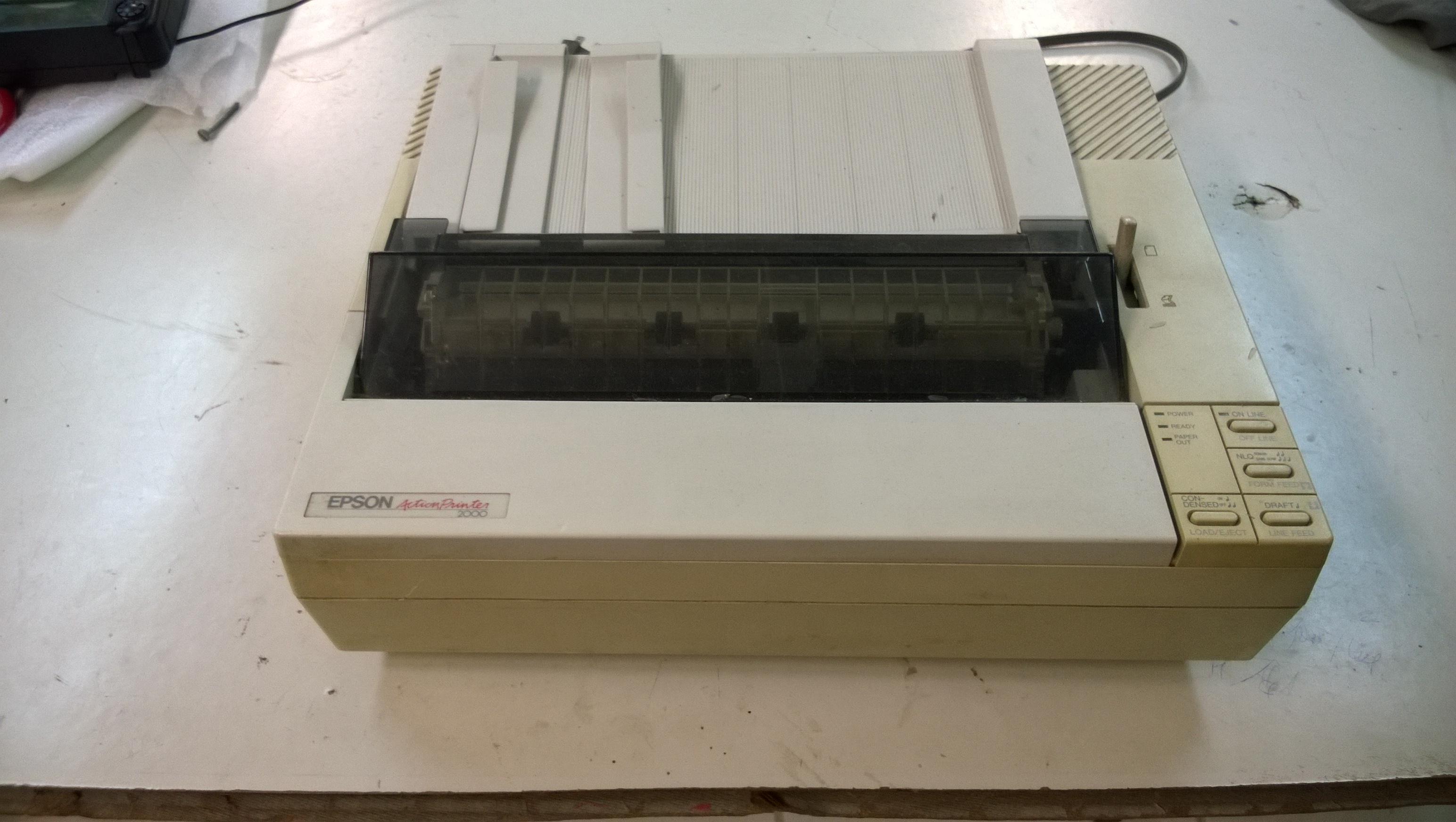
The ribbon was dry, but the printer still worked, so we bought a new ribbon and started having fun printing out ASCII-art stuff.

The ActionPrinter 2000 offers a few different kinds of fonts and modes: Draft, Near Letter Quality (Roman and Sans Serif), condensed mode, 12 characters per inch, 10 characters per inch, subscript, superscript… It occurred to me that the font used for the ASCII-art conversion programs was hardcoded, and probably didn’t relate to the one used in the ActionPrinter 2000.

So I was interested in mapping out the character bitmaps to get a better ASCII-art conversion. My first thought was: “let’s get a magnifying glass and map the characters dot by dot!”.

Mapping the dots using magnifying glass

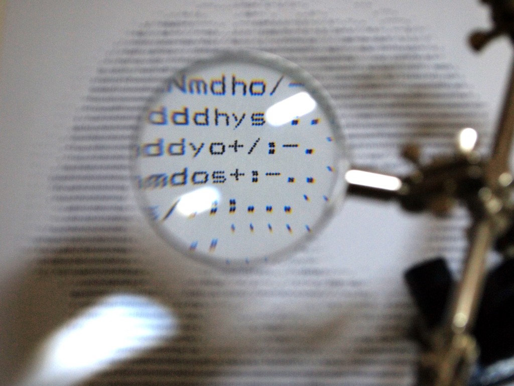
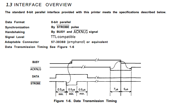
Sure, that worked, but it was time consuming and not the smartest way… There should be some better way. To print out the dots, at some point there must be an electrical signal being sent to the printhead for each dot. So, what if I intercepted that signal and used it to map out the characters?

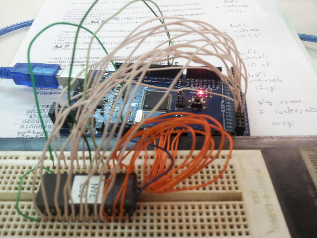
I opened up the printer and looked for the printhead connector. But then I found a 27c256 EPROM inside, which likely contained the firmware. Hey, the firmware has all the characters inside it somewhere, that’s better than fiddling with the printhead. I got the 27c256’s datasheet and used an Arduino Mega to dump its contents.

Dumping the 27c256 EPROM with an Arduino Mega

After reading through the dump for quite some time, I found some bitstreams that looked like characters, but they weren’t very well organized, so I couldn’t make sense of their structure. Then I remembered that the last time I had visited Garoa Hackerspace, it was Retroprogramming night, and Felipe “Juca” Sanches was talking about emulating old hardware using MAME/MESS. Well, what if I emulated the firmware and recorded the data before it was sent to the printhead?

So I started fiddling around with MESS. It already had some incomplete drivers for the Epson LX-800 and Epson EX-800 printers. I used them as a basis to get my head around the MESS codebase and add support for the ActionPrinter 2000. It shouldn’t be so hard, right? (whenever I ask “right?”, the answer is “wrong”).

So I added the ActionPrinter 2000 firmware and fired up MESS. The processor hanged. I spent some time looking for buttons or switches being read by MESS, maybe just tweaking them would get past the hang. That wasn’t the case, it would still hang and there was no way out of it. Now, if only I had a debugger to see what was wrong… Oh, MESS has a debugger.

MAME/MESS debugger

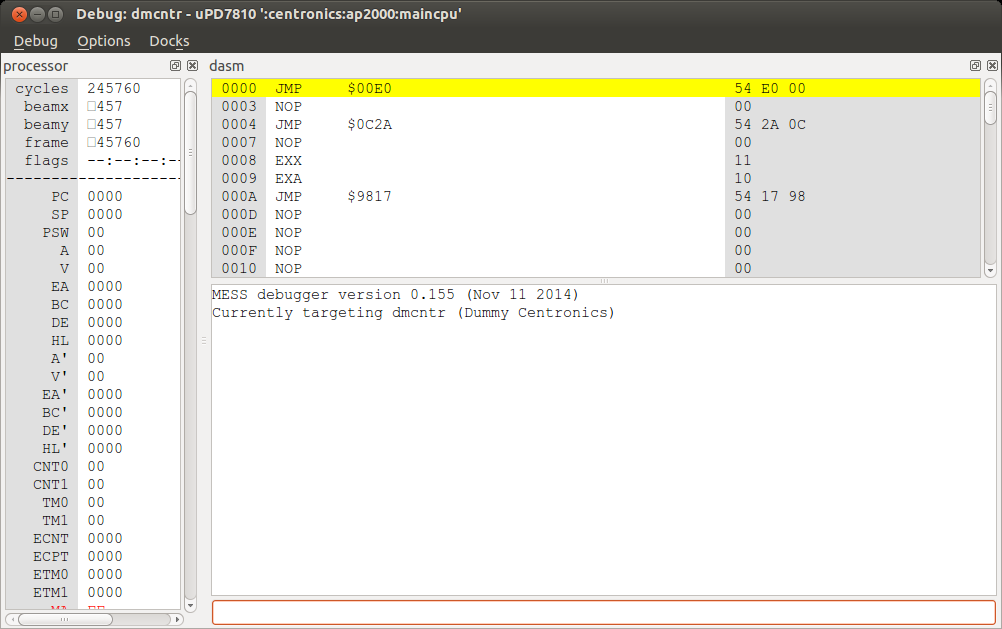
So, the ActionPrinter 2000 uses an uPD7810 processor. I needed to get its datasheet to understand the assembly. After stepping through the assembly for quite some time, I realized the uPD7810 emulation in MESS was lacking a few functions. There was no ADC support, which was necessary to read the input voltage and some switches. If the printer’s input voltage was too low, the printer would not boot.

So I implemented ADC support, and the firmware would just hang again a few instructions later. What was wrong this time? An interrupt wasn’t being set inside the processor. Who should be setting that interrupt?

I had already started reverse-engineering the printer’s hardware, but now I knew it was important to map all hardware connections in MESS. There were many other integrated circuits: a gate array (E05A30), a RAM chip (2064C), a 256-bit EEPROM (93c06), a stepper motor driver (SLA7020M), and others…

The gate array that was partly implemented in MESS was the E05A03, not the E05A30. It’s a custom-made gate array, and works pretty much like a black box. There’s no way to find out what goes on inside if you don’t have access to the datasheets (which I didn’t). I created some skeleton code for the E05A30 gate array for MESS.

I found out the interrupt that wasn’t being set should have been set by the gate array. So I added an interrupt request right after the gate array started.

I got a few more instructions being run and the firmware would hang again. At this point it was getting complicated having to read the assembly all the time, so I started manually decompiling the firmware. It is a 32 KB firmware. It shouldn’t take too long, right? (remember: the answer is “wrong”)

With a bit of decompiled code, I got this snippet:

void reset_ram(uint8_t val)
{
	memset(0x9800, val, 0x2000);
	if (*((uint8_t *)0xb7ff) != 0xff) {
		killall();
		beep(4, 2);
		while(1); /* HANG */
	}
}

void _start()
{
	[...]
	reset_ram(0xff);
	reset_ram(0x00);
	[...]
}

That didn’t make much sense to me. The RAM was only 8 KB, starting at 0x8000 and ending at 0xa000. There should be nothing at 0xB7FF. Even if there was something, it was being set to 0xFF and then to 0x00, but the data was expected to stay at 0xFF. It might be something inside the gate array, I don’t know. I just created a fake memory device that worked just as was expected for the emulator to be happy.

I got some more instructions, but it entered an infinite loop. Hey, that’s better than hanging…

After much more debugging and decompiling, I realized that the printer was outputting some commands to the gate array in a loop. There were 8 commands being sent and there would be a check for a sensor in the board. I looked at the sensor in the printer, and it turned out to be the Home sensor, i.e. whether the printhead was back at position 0. The command sequence being sent looked very familiar, like the phase signals for a stepper motor. MESS already had stepper motors implemented. I just needed to adapt the command sequence, because it passed through the SLA7020M before reaching the motor. And then I got this:

:__________@_______________________________:
:_________@________________________________:
:________@_________________________________:
:_______@__________________________________:
:______@___________________________________:
:_____@____________________________________:
:____@_____________________________________:
:___@______________________________________:
:__@_______________________________________:
:_@________________________________________:
:@_________________________________________:
:_@________________________________________:
:__@_______________________________________:
:___@______________________________________:
:____@_____________________________________:
:_____@____________________________________:
:______@___________________________________:
:_______@__________________________________:
:________@_________________________________:
:_________@________________________________:
:__________@_______________________________:
:___________@______________________________:
:____________@_____________________________:
:_____________@____________________________:
:______________@___________________________:
:_______________@__________________________:
:________________@_________________________:
:_________________@________________________:
:__________________@_______________________:
:___________________@______________________:
:____________________@_____________________:

This is a printf() of the motor seeking home and going back to the middle of the page. The printer was finally starting to work! This was awesome!

But then, the printer would get into an infinite loop again. It was waiting for the Online button to be pressed, but it wasn’t being acknowledged by the processor. That’s when I realized that the button should trigger an interrupt, which wasn’t properly implemented in MESS. So I implemented the interrupt properly and pressed the Online button.

According to the printer’s User Manual, now the printer should be pulling paper. Indeed, I noticed a different command sequence being sent (for the Paper Feed stepper motor). Now I had both motors working.

What was the next step? Entering the input loop. I should be able to send commands to the printer and have it print them out to paper.

At this moment we take a little pause. We need to realize that the work up to here has already taken me many months. It may seem simple when being read in a blog post, but it was a lot of hard work.

So, instead of going for the input loop, I decided to use the printer’s self-test function. While running the self-test function, I got more commands being sent to the gate array. I suspected they were the printhead signals (the ones I was after right when I started this). Indeed, they seemed like characters, but there was a problem: the printhead wasn’t being fired. After some debugging, I noticed that the timer which would fire the printhead was incorrectly implemented in MESS, so I had to fix that.

Finally, I had a bunch of stuff being printed. I wrote a little script to organize that stuff into an image, and then I got this:

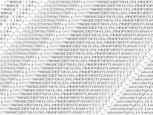
I finally got my characters.

The code can be found in my GitHub account, inside the MAME repository and the lx810l branch. It should be merged into MAME upstreams in a few days. To run the self-test, build the dummy_centronics subtarget from the lx810l-debug branch.

By the way, the characters matched the ones I got with the magnifying glass…